Parallel Beam X-ray Optics: Grazing Incident X-ray Diffraction (GIXRD) and X-ray Reflectivity (XRR)
Author: David W. Mogk, Montana State University, NNCI/MONT co-PI

Incident and diffracted Xrays in Bragg Brentano Xray optic geometry
![[reuse info]](/images/information_16.png)
Provenance: NIST; from Cline, J.P., Mendenhall, M.H., Black, D., Windover, D. and Henins, A., 2015. The optics and alignment of the divergent beam laboratory X-ray powder diffractometer and its calibration using NIST standard reference materials. Journal of research of the National Institute of Standards and Technology, 120, p.173.
Reuse: This item is in the public domain and maybe reused freely without restriction.
Powder X-ray Diffraction is typically used to determine the atomic structure of crystalline materials in three dimensions. A
divergent X-ray beam in "Bragg-Brentano" geometry is used to produce diffraction patterns for phase identification, determination of lattice parameters, degree of crystallinity, and grain size and texture features. The high intensity X-ray beam samples a large volume of crystalline material with relatively large penetration depth of the X-rays that produce high resolution diffraction patterns; this geometry is relatively insensitive to the atomic structure of thin layers (a few atomic layers on a nanometer scale) on the outer surfaces of materials. Acquisition of XRD data requires careful sample preparation to produce random grain orientation so that all principal atomic planes in the material are diffracted. It is also sensitive to sample positioning such that the analyzed surface and focal point of the incident beam must be well-aligned in the same plane. X-ray diffractometers are typically set up in
θ -
θ mode, where the sample remains stationary in a horizontal position, and the X-ray source and detector move at the same rate (degrees/minute), or in
θ - 2
θ mode where the X-ray source is fixed, the sample moves at
θ degrees/minute and the detector moves at 2
θ degrees/minute.

Incident and diffracted Xrays in Parallel Beam Xray optic geometry
![[creative commons]](/images/creativecommons_16.png)
Provenance: Yale University West Campus materials Characterization Core, https://ywcmatsci.yale.edu/principle-0
Reuse: This item is offered under a Creative Commons Attribution-NonCommercial-ShareAlike license http://creativecommons.org/licenses/by-nc-sa/3.0/ You may reuse this item for non-commercial purposes as long as you provide attribution and offer any derivative works under a similar license.
In contrast,
Parallel Beam X-ray optics compensates for issues of sample flatness, roughness, and positioning (e.g., non-destructive analyses of irregular materials such as art artifacts and machine parts can be obtained). Because Bragg-Brentanno X-ray optics use a divergent beam that must be positioned on the focusing circle, errors may be introduced due to misalignment of sample height, the sample surface is not curved to be aligned with the focusing circle, so a divergent beam can not be fully aligned, and the X-ray footprint is a function of the angle of incidence and the diffracted X-rays may come from depths not on the focal circle; these errors are minimized with parallel beam X-ray optics (Harrington and Santiso, 2021).Parallel beam configuration is particularly amenable for
analysis of material surfaces on the order of 1's to 100's of nanometers, including thin films and coatings, phase identification of surface materials, and surface textures. A grazing or small angle of incidence is typically used so that only the outermost atomic layers are sampled for analysis. Depth sensitivity can be achieved by increasing the angle of incidence of the X-ray beam in small increments to sample increased depths into the materials. It becomes possible to obtain depth profiles of phases on material surfaces and to measure multi-layers on material surfaces.
Two parallel beam X-ray methods are commonly used to characterize material surfaces:
- Grazing Incident Diffraction (GID)--used to identify phases present on material surfaces on a nanometer scale; and,
- X-ray Reflectometry (XRR)--used to determine the thickness, density and surface roughness of material surfaces.
GID and XRR provide complementary information about the thin film structure, with crystallographic information from GID
and layer morphology by X-ray reflectivity, including surface roughness and layer thickness.
Although widely used in disciplines such as material science, metallurgy, ceramics, and pharmaceuticals, these methods have not been widely applied to Earth materials. Numerous surface-mediated reactions common in the Earth system can be studied using GID and XRR: sorption, catalysis, redox, dissolution/precipitation, chemical weathering and much more. Phases present on material surfaces may go completely undetected using traditional Bragg-Brentano X-ray optics due to the larger signal that derives from deep penetration of the beam into the sample. GID and XRR grazing incident methods may be some of the few methods available to characterize phases on the outermost few nanometers on material surfaces--although small, these surface materials may provide essential information on geochemical processes, rates, and pathways! Information derived from GIXRD and XRR analyses provide information on the average structural state of material surfaces and may be integrated with other imaging methods such as scanning electron microscopy, transmission electron microscopy, and atomic force microscopy to gain more site-specific information.
Grazing Incident X-ray Diffraction (GID or GIXRD)

Schematic diagram of Grazing Incident X-ray Diffraction (GIXRD)
Provenance: Unknown.
Reuse: This item is offered under a Creative Commons Attribution-NonCommercial-ShareAlike license http://creativecommons.org/licenses/by-nc-sa/3.0/ You may reuse this item for non-commercial purposes as long as you provide attribution and offer any derivative works under a similar license.
Characterization of thin films and coatings on material substrates can be accomplished using parallel beam X-ray optics and Grazing Incident Diffraction. X-ray diffraction is one of the standard methods used to determine the crystalline structure of solid materials. However, conventional X-ray methods using Bragg-Brentano divergent beam X-ray optics sample the "bulk" of the material on the order of microns deep. Any thin films or coatings on a material surface will be effectively transparent to this mode of analysis. In contrast, parallel X-ray beam methods, using low angle incident X-ray beams (~1-3 degrees) are very sensitive to the near-surface region (10s to ~200 nanometers) and the identity of surface phases can be determined based on crystal structure determinations. GIXRD allows the crystalline features of surfaces and thin films to be determined. As the angle of incidence varies to larger angles, the depth of penetration of the beam increases and a resulting series of diffractograms can reveal the presence of one or more thin film layers deposited on a substrate. It is often the case that the physical and chemical properties of thin films will diverge greatly with the properties of the underlying "bulk" substrate material. Thus, there is a great necessity to utilize methods to uniquely characterize the properties of these thin films, and GIXRD is an efficient, non-destructive method to do so. Due to the low intensity of diffracted X-rays at material surfaces, high energy sychrotron X-ray sources have traditionally been used to acquire GIXRD data. However, advances in X-ray beam sources and the efficiency of detectors now make it possible to collect these data using stand-alone, lab-based X-ray diffractometers. In addition to analysis of crystalline phases on material surfaces,
Achilli et al. (2022) have recently demonstrated the utility of GIXRD to obtain quantitative information about the composition of amorphous mixed oxides.
Applications

SEM Image of oxide coating on Zinc, figure 4 from Vourlias, G., 2020. Application of X-rays diffraction for identifying thin oxide surface layers on zinc coatings. Coatings, 10(10), p.1005.
Provenance: Figure from Vourlias, G., 2020. Application of X-rays diffraction for identifying thin oxide surface layers on zinc coatings. Coatings, 10(10), p.1005.
Reuse: This item is offered under a Creative Commons Attribution-NonCommercial-ShareAlike license http://creativecommons.org/licenses/by-nc-sa/3.0/ You may reuse this item for non-commercial purposes as long as you provide attribution and offer any derivative works under a similar license.
GID is widely used in material sciences where thin films play a prominent role in engineered and synthetic materials developed to control electrical, microstructural and optical properties with applications to materials such as energy devices, sensors, catalysts, protective coatings designed to protect against thermal and mechanical degradation, and reflection and sorption of light on optical devices. Diffraction spectra can be used for identification of phases on material surfaces, and crystalline size may be estimated by measuring peak broadening as represented by the full width half maximum (FWHM) of the peaks. GID has not been widely used in characterizing natural materials in the Earth and Environmental Sciences, but this is an area of great research potential as there is a need to identify the products of surface-mediated reactions controlled by dissolution/precipitation, redox, sorption, catalytic processes, and epitaxial overgrowths of minerals.
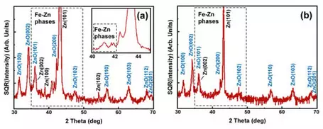
Figure 5. GI-XRD diffraction pattern of the hot-dip galvanized samples using an incidence angle of (a)
5◦ and (b) 1.5◦. From Vourlias, G., 2020. Application of X-rays diffraction for identifying thin oxide surface layers on zinc coatings. Coatings, 10(10), p.1005.
Provenance: Figure 5. GI-XRD diffraction pattern of the hot-dip galvanized samples using an incidence angle of (a) 5◦ and (b) 1.5◦. From Vourlias, G., 2020. Application of X-rays diffraction for identifying thin oxide surface layers on zinc coatings. Coatings, 10(10), p.1005. Used by Creative Commons license.
Reuse: This item is offered under a Creative Commons Attribution-NonCommercial-ShareAlike license http://creativecommons.org/licenses/by-nc-sa/3.0/ You may reuse this item for non-commercial purposes as long as you provide attribution and offer any derivative works under a similar license.
The advantages of using GIXRD include:
- non-destructive method
- no extensive sample preparation is needed;
- can be done in gaseous, liquid and vacuum environments
- allows for rapid data acquisition
- phase identification of ordered crystal structures on material surfaces, preferred orientation of crystals, epitaxial overgrowths, micro-strain in materials through careful analysis of peak positions, grain size distribution, polymorphic transitions due to dynamically changing chemical or physical conditions (typically in an environmental chamber), and multilayered structures can be resolved for buried interfaces (e.g., semiconductor layers) (Werzer et al., 2024)
- can be used under a variety of experimental, non-ambient conditions for in situ measurements under conditions of high vacuum, high gas pressure, electrochemical set-ups, and during active deformation (Werzer et al., 2024),
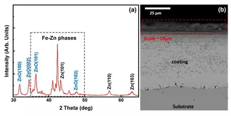
Figure 10. (a) GI-XRD pattern and (b) SEM micrograph of the oxidized hot-dip coating. From Vourlias, G., 2020. Application of X-rays diffraction for identifying thin oxide surface layers on zinc coatings. Coatings, 10(10), p.1005.
Provenance: Figure from Figure 10. (a) GI-XRD pattern and (b) SEM micrograph of the oxidized hot-dip coating. From Vourlias, G., 2020. Application of X-rays diffraction for identifying thin oxide surface layers on zinc coatings. Coatings, 10(10), p.1005. Used under Creative Commons license.
Reuse: This item is offered under a Creative Commons Attribution-NonCommercial-ShareAlike license http://creativecommons.org/licenses/by-nc-sa/3.0/ You may reuse this item for non-commercial purposes as long as you provide attribution and offer any derivative works under a similar license.
Limitations and practical considerations include:
- Flat surfaces are required as the material substrate
- Spatial resolution is poor, and information derives, and is averaged, over a large surface area (mm2);
- Careful alignment of the sample and beam is required, such that the sample is positioned in the horizontal plane and at the correct height for focus of the incident beam. "Typical alignment errors include the sample surface not being located at the centre of the goniometer with respect to the desired rotation axis and translational z height; an incorrect incident angle" (Werzer et al., 2024).
- GIXRD has limited spatial resolution, and due to the small angle of incidence a long stripe of the sample is analyzed over a large area (the X-ray 'footprint'), with results that provide information on the average atomic structure;
- For very thin films with small mean atomic number, the X-ray scattering power is very weak, so this application may be limited or impossible.
How GIXRD Works
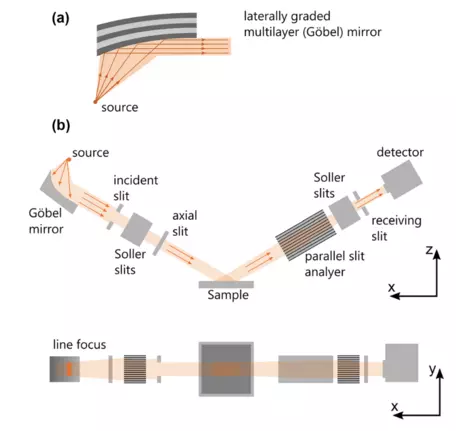
Example of parallel X-ray beam optics instrument configuration. From Harrington, G.F. and Santiso, J., 2021. Back-to-Basics tutorial: X-ray diffraction of thin films. Journal of Electroceramics, 47(4), pp.141-163.
Provenance: Figure from: Harrington, G.F. and Santiso, J., 2021. Back-to-Basics tutorial: X-ray diffraction of thin films. Journal of Electroceramics, 47(4), pp.141-163.
Reuse: This item is offered under a Creative Commons Attribution-NonCommercial-ShareAlike license http://creativecommons.org/licenses/by-nc-sa/3.0/ You may reuse this item for non-commercial purposes as long as you provide attribution and offer any derivative works under a similar license.
Instrument Configuration: A standard lab-based powder X-ray diffractometer can be used to obtain GIXRD data. An XRD instrument can be equipped with a Gobel (parabolic) mirror to produce parallel X-ray beams which results in less loss of X-ray intensity and also reduces the K
β X-ray energy; alternately, very small divergent slits can be used with plate collimators to reduce divergence of the X-ray beam, and a parallel plate collimator is needed for the diffracted beam (Harrington and Santiso, 2021). Soller slits are also needed to reduce axial divergence of the beam. An adjustable sample stage is required to very precisely position the sample surface at the correct analytical height on the focusing circle. "In GIXRD, the incidence angle, 𝜔 , is fixed to a small angle of approximately 0.5–1°, slightly above the critical angle (below which total reflection will occur), and the detector is moved on the 2𝜃-circle to collect the pattern. In this way the penetration deeper into the sample is considerably reduced and the intensity of the film peaks is enhanced with respect that of substrate" ((Harrington and Santiso, 2021). By varying the incidence angle it is possible to change the X-ray penetration depth to obtain structural information at varying depths in the sample.
A monochromatic X-ray beam is used at a grazing angle of incidence, φ, that is close to the critical angle for total reflection. To minimize the depth of penetration of the X-rays into a material surface, all that is required is to reduce the angle of incidence φ so the diffracted X-rays will emanate only from the outermost atomic layers. According to Gibson (2011), "The index of refraction of solid and liquid materials at typical X-ray wavelengths is slightly less than unity; thus, at low angles of incidence refraction becomes significant, and below a critical angle ϕc total external reflection occurs, such that the effective penetration of the evanescent wave into the material decreases to a few nanometers." There is a rapid change in the penetration depth at the critical angle of incidence, φc, such that surface sensitivity is only achieved at low incident angles. However, this also means that the intensity of the diffracted beam is also greatly reduced at incident angles below φc which is why GIXRD has traditionally been limited to synchrotron X-ray sources. High resolution GIXRD data may be acquired by appropriate instrumental setup: "The best signal-to-noise ratio can be achieved by long integration times or by reducing background scattering. Using slits close to the sample on both the primary and diffracted beams has a major influence in reducing stray reflections (Werzer et al., 2024). Most vendors of modern X-ray diffraction instruments provide the required hardware (Gobel mirror, collimators and slits, sample stages for precise alignment, high efficiency detectors) and software packages required to do in-lab GIXRD experiments. See: Bruker, Rigaku, Panalytical.
Sample selection and preparation is essential to successfully conduct GIXRD experiments. Samples are typically mounted in a horizontal orientation. The sample should be large enough so that the signal derives only from the sample surface while avoiding edge effects. The samples must also be flat and smooth to obtain resolvable surface diffraction patterns. The optimal angle of incidence φ will be sample dependent and related to the critical angle of that material.
For a polycrystalline material on the surface, a typical diffraction pattern can be obtained, similar to what can be obtained in Bragg-Brenano mode. The incident angle φ is fixed at a low angle to the sample which also remains fixed in a horizontal orientation and the detector is rotated by 2φ to obtain the diffraction pattern. It may be necessary to experiment by varying the incident angle a bit to optimize results. The diffraction pattern can then be used to index peaks to known standard databases (e.g., ICDD) to identify phases on the material surfaces.
If the surface material has a strong preferred orientation of micro-grains, it may not be possible to obtain diffraction patterns to satisfy the Bragg condition. However, the relative peak intensities can possibly be used to determine crystal orientation information relative to the substrate (Werzer et al., 2024). It may be possible to also obtain average crystallite size determinations by analysis of the degree of peak broadening. This is based on the Debye-Scherrer equation:
D = K λ/β cosθ,
where D is the crystalline size, K = 0.9, λ = 0.154 nm and β is the full width at half maximum of the peak located at Bragg angle θ (Klug and Alexander, 1974).
X-ray Relectivity (XRR)

Schematic figure of X-ray Reflectivity (XRR)
Provenance: Unknown.
Reuse: This item is offered under a Creative Commons Attribution-NonCommercial-ShareAlike license http://creativecommons.org/licenses/by-nc-sa/3.0/ You may reuse this item for non-commercial purposes as long as you provide attribution and offer any derivative works under a similar license.
As light rays will reflect and scatter from ripples on a lake, so too will X-rays reflect from irregular material surfaces. This is the basis of X-ray reflectivity (XRR). There are three primary types of information that can be derived from XRR curves: 1)
density, which is determined by the position of the critical angle associated with total reflection condition which is a function of the density of the material on the surface; 2)
surface layer thickness which is revealed by the frequency of oscillations in the data that are generated by the deposited films (commonly referred to as "Kiessig fringes" where the oscillation depends on the film thickness, and the thicker the film, the shorter period of the oscillations and 3)
surface roughness which is related to the decay of the XRR signal; reflected X-rays decrease more rapidly with a larger surface roughness. In other words, the larger the roughness of a film, the faster the decay rate of X-ray reflectivity. Related to the discussion of GIXRD above, reflection of an X-ray beam occurs at angles of incidence above the critical angle
φc, and this reflection will occur at any interface of materials that have different refractive indices. The reflectivity coefficient at an interface is dependent on the roughness of the interface and density of materials on either side of the interface. Samples should be very smooth and flat with surface roughness less than a few hundred nanometers. Thus, the dominant use of this method in characterizing thin film and coatings on very flat substrates such as Si chips and semiconductors. When configured with parallel beam X-ray optics, XRR data can be obtained from standard lab-based X-ray diffractometers (Huang et al., 2013).
Applications
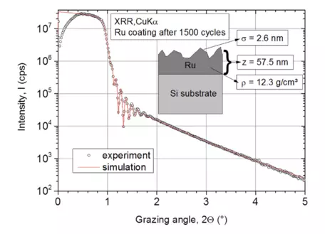
X-ray reflectometry (XRR) measurement on atomic layer deposition (ALD) Ru layer and
corresponding simulation with a simple two-layer model (substrate + Ru thin film). Figure 1 from Müller et al., 2018.
Provenance: Figure 1 from: Müller, R., Ghazaryan, L., Schenk, P., Wolleb, S., Beladiya, V., Otto, F., Kaiser, N., Tünnermann, A., Fritz, T. and Szeghalmi, A., 2018. Growth of atomic layer deposited ruthenium and its optical properties at short wavelengths using Ru (EtCp) 2 and oxygen. Coatings, 8(11), p.413.
Reuse: This item is offered under a Creative Commons Attribution-NonCommercial-ShareAlike license http://creativecommons.org/licenses/by-nc-sa/3.0/ You may reuse this item for non-commercial purposes as long as you provide attribution and offer any derivative works under a similar license.
XRR is the only technique that can provide non-destructive information on the electron density of material surfaces, and that can detect and characterize interfaces below material surfaces. Thus, this method has become an indispensable tool to analyze thin films and coatings on a sub-micron to atomic scale. There are many important applications of XRR to engineered materials also, such as characterization of semiconductors, products of (molecular beam) epitaxy, and development of thin coatings designed to mitigate chemical and physical corrosion. Application of XRR to natural samples may be somewhat limited due to requirements of very flat initial samples; however, experiments using properly prepared substrates could be applied to processes such as the formation of desert varnish, chemical weathering, and biomineralization. X-ray Porosimetry also becomes possible using XRR as porous films will be less dense and will consequently have a well-defined and distinct critical angle (Gibaud et al., 2013).
How XRR works

Provenance: Dave Mogk, Montana State University-Bozeman
Reuse: This item is offered under a Creative Commons Attribution-NonCommercial-ShareAlike license http://creativecommons.org/licenses/by-nc-sa/3.0/ You may reuse this item for non-commercial purposes as long as you provide attribution and offer any derivative works under a similar license.
Reflectivity is the result of X-ray - material interactions that are related to the index of refraction, and thus the critical angle, of the material in question. X-ray radiation has a refractive index that is slightly less than 1 as X-rays pass from air (n=1) to a reflecting material (n<1). Consequently, it is possible to totally reflect X-rays if the incident angle is smaller than the critical angle
θc, an effect known as total external reflection (Gibaud et al., 2013). Part of the X-ray energy is reflected from a flat surface, and part is transmitted through the material. The incident X-ray will be symmetric with the direction of the reflected X-ray and this is referred to as specular reflectance. Most surfaces are not ideally flat, and very small aberrations to the surface flatness (i.e., roughness) will be less reflecting. Acquired XRR data are compared to model output determined by least-squares method to fit the XRR curve to the measured data to determine the surface material density based on determination of the critical angle, the thickness of layer(s) which requires applying a Fourier transform of the Kiessig fringes (e.g., Lammel et al., 2020), and the number of oscillations to determine surface roughness. Dedicated software such as the Bruker
DIFFRAC.XRR program is needed to fully analyze XRR data.
You Can't See If You Don't Look
As an example, the Montana Microfabrication Facility made a thin film of Ti on a Si (001) wafer using an electron beam evaporator at 1 A/s at pressures of about 1e-6 Torr to deposit a layer of ~10 nm thickness. This material will have some amount of native SiO2 formed from being in contact with air. We used the Bruker Advance D8 powder diffractometer configured for parallel X-ray beam capabilities housed at the Imaging and Chemical Analysis Laboratory to acquire GIXRD and XRR data. These results were then compared to Auger Electron Spectroscopy depth profiles. Key results are:
- Two GID profiles are superimposed: one from the Si(001) wafer (red) and another from Ti/Si(001) interface (black) obtained by keeping the incidence x-rays at 2o incidence. The spectrum is dominated by the Si (311) diffraction peak as this is a single crystal substrate and this is the only diffracting plane that meets the Bragg condition.
- The XRR profile is complex and does not represent a single smooth interface layer. This complex reflectivity spectra is pending a comprehensive analysis.
- The Auger Nanoprobe depth profile was obtained using 500 eV Ar+ ions at 0.8 mA target current by monitoring the AES peaks of O, Ti, C and Si. The depth profile shows a complicated layer structure starting with surface oxidation of the Ti film followed by pure Ti and a zone of elemental mixing of Ti and Si from ~3-6 nm depth, which was suggested by the reflectivity spectra shown in the middle Figure. Notice the native silicon oxide film at 2 nm marking the surface of the Si-wafer.
Without obtaining the GID and XRD data, the structural complexities of this surface would go undetected.
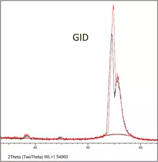
Ti thin film on Si wafer measured by GID. Data from Montana State University, Imaging and Chemical Analysis Laboratory.
Provenance: Dave Mogk, Montana State University-Bozeman
Reuse: This item is offered under a Creative Commons Attribution-NonCommercial-ShareAlike license http://creativecommons.org/licenses/by-nc-sa/3.0/ You may reuse this item for non-commercial purposes as long as you provide attribution and offer any derivative works under a similar license.
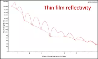
Ti thin film on Si wafer measured by XRR. Data from Montana State University, Imaging and Chemical Analysis Laboratory.
Provenance: Dave Mogk, Montana State University-Bozeman
Reuse: This item is offered under a Creative Commons Attribution-NonCommercial-ShareAlike license http://creativecommons.org/licenses/by-nc-sa/3.0/ You may reuse this item for non-commercial purposes as long as you provide attribution and offer any derivative works under a similar license.
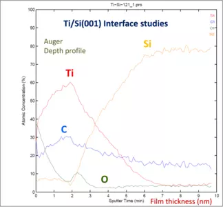
Ti thin film on Si wafer measured by AES. Data from Montana State University, Imaging and Chemical Analysis Laboratory.
Provenance: Dave Mogk, Montana State University-Bozeman
Reuse: This item is offered under a Creative Commons Attribution-NonCommercial-ShareAlike license http://creativecommons.org/licenses/by-nc-sa/3.0/ You may reuse this item for non-commercial purposes as long as you provide attribution and offer any derivative works under a similar license.
An Example Using GIXRD and XRR (application to engineered and natural materials)
Płacheta et al. (2023) studied growth of titanium oxide thin films grown on a variety of substrates (e.g., In-Sn oxide; a variety of amorphous Si glasses) by magnetron sputtering under ultra-high vacuum conditions, at temperature of 350oC and under variable O2/Ar gas ratios. Possible titanium oxide phases include: TiO, TiO2 (tetragonal rutile [primitive] and anatase [body centered] crystal structures), Ti2O3 and Magnéli phases TinO2n-1. Results are reported for analytical results using GIXRD, XRR, SEM, XPS and X-ray Absorption Spectroscopy (XAS). Crystal structure of the thin films was determined using GIXRD methods with angle of incidence set at 0.5, 1, and 2 degrees, and collecting diffraction data from 15o to 75o. Phase identification was done by comparing them to reference diffraction patterns in the ICDD database. Crystallite sizes were determined using the Debye-Scherrer equation and confirmed by SEM imaging and image processing using the imageJ software. XRR was used to determine the surface phase density, thickness and roughness. See experimental results:

GID-XRD patterns of titanium oxide thin films from Platcheta et al. (2023).
Provenance: Figure from Płacheta, K., Kot, A., Banas-Gac, J., Zając, M., Sikora, M., Radecka, M. and Zakrzewska, K., 2023. Evolution of surface properties of titanium oxide thin films. Applied Surface Science, 608, p.155046. Available through Creative Commons license.
Reuse: This item is offered under a Creative Commons Attribution-NonCommercial-ShareAlike license http://creativecommons.org/licenses/by-nc-sa/3.0/ You may reuse this item for non-commercial purposes as long as you provide attribution and offer any derivative works under a similar license.
Fig. 1. GID-XRD patterns of titanium oxide
thin films deposited at 5–30 % of O
2/(O
2 + Ar) flow ratio, recorded at the incidence angle ω = 2° after subtraction of the background signal. Crystallographic phases of TiO, Ti
2O
3, rutile (R), anatase (A) and brookite (B) have been identified.

Placheta et al. (2013) Fig. 2. GID-XRD patterns of TiO2 films deposited at 10, 15, 17.5 and 30 % O2/(O2 + Ar) recorded at incidence angles ω: 0.5, 1 and 2°. Positions of reference peaks for identified crystallographic phases, i.e., anatase and rutile, are marked by vertical lines based on ICDD database.
Provenance: Figure from łacheta, K., Kot, A., Banas-Gac, J., Zając, M., Sikora, M., Radecka, M. and Zakrzewska, K., 2023. Evolution of surface properties of titanium oxide thin films. Applied Surface Science, 608, p.155046. Used under Creative Common license.
Reuse: This item is offered under a Creative Commons Attribution-NonCommercial-ShareAlike license http://creativecommons.org/licenses/by-nc-sa/3.0/ You may reuse this item for non-commercial purposes as long as you provide attribution and offer any derivative works under a similar license.
"X-ray radiation penetrates through the layer. This creates a strong background signal centered at low 2θ angles (15-30°), recorded from the amorphous SiO
2 substrate, as shown in
Fig. 2. XRD patterns taken at small ω angles of the incident beam in GID configuration allow to probe the film surface." For each treatment (A,B,C,D) "there is no significant difference in the crystal structure between the bulk and the surface of all deposited films. Therefore, it can be concluded that the films are homogenous from the point of phase composition." Fig. 2. GID-XRD patterns of TiO
2 films deposited at 10, 15, 17.5 and 30 % O
2/(O
2 + Ar) recorded at incidence angles ω: 0.5, 1 and 2°. Positions of reference peaks for identified crystallographic phases, i.e., anatase and rutile, are marked by vertical lines based on iCDD Database.

Platcheta et al. (2013) Fig. 3. Crystallite size calculated from Debye-Scherrer equation
Provenance: Figure from Płacheta, K., Kot, A., Banas-Gac, J., Zając, M., Sikora, M., Radecka, M. and Zakrzewska, K., 2023. Evolution of surface properties of titanium oxide thin films. Applied Surface Science, 608, p.155046. Used under Creative Common License.
Reuse: This item is offered under a Creative Commons Attribution-NonCommercial-ShareAlike license http://creativecommons.org/licenses/by-nc-sa/3.0/ You may reuse this item for non-commercial purposes as long as you provide attribution and offer any derivative works under a similar license.
Fig. 3.
Crystallite size (squares) are calculated from Debye-Scherrer equation superimposed on phase fraction of anatase f
A (blue bar) and rutile f
R (red bar) for samples deposited at 5–30 % of O
2/(O
2 + Ar) flow ratio. "At low (5–10 %) values of O
2/(O
2 + Ar) flow ratio, when the transformation from TiO to fine-grain TiO
2 through Ti
2O
3 occurs, crystallite size decreases. The smallest crystallite size in the whole series appears for fine-crystallized rutile obtained at 10 %. Then, with an increase in the O
2/(O
2 + Ar) flow ratio from 10 to 20 %, a growth of rutile
crystallites can be observed. When rutile almost disappears at 25 % of O
2/(O
2 + Ar), the anatase crystallites reach the highest size of about 18 nm. Further growth of the anatase crystallites at high oxygen ratio (30 %) is inhibited."

Placheeta et al. (2013) Fig. 4. SEM images of thin films sputtered at low (5, 7.5 and 10 %) values of O2/(O2 + Ar) flow ratio
Provenance: Figure from Płacheta, K., Kot, A., Banas-Gac, J., Zając, M., Sikora, M., Radecka, M. and Zakrzewska, K., 2023. Evolution of surface properties of titanium oxide thin films. Applied Surface Science, 608, p.155046. Used under Creative Commons License.
Reuse: This item is offered under a Creative Commons Attribution-NonCommercial-ShareAlike license http://creativecommons.org/licenses/by-nc-sa/3.0/ You may reuse this item for non-commercial purposes as long as you provide attribution and offer any derivative works under a similar license.
"Surface of all deposited films is composed of small grains that in fact reflect the shape of caps at the top of the fibers or columns grown more or less vertically to the substrate, as can be seen in the cross-sectional images. The grain size is therefore understood as a diameter of top of the fiber or column, determined from the analysis of top view images. Uniform distribution of grains for each film obtained at a given O
2/(O
2 + Ar) flow rate ratio, allows one to conclude homogenous covering of the Si substrate for all layers. However, the fiber or column diameter changes drastically when O
2/(O
2 + Ar) flow ratio is varied." Fig. 4. SEM images of
thin films sputtered at low (5, 7.5 and 10 %) values of O
2/(O
2 + Ar) flow ratio: surface (left column: a, c, e) and cross-sectional views (right column: b, d, f).

Placheta et al. (2013) Fig. 5. SEM images of thin films sputtered at higher (15, 17.5 and 30 %) values of O2/(O2 + Ar) flow ratio: surface (left column: a, c, e) and cross-sectional views (right column: b, d, f).
Provenance: Figure from Płacheta, K., Kot, A., Banas-Gac, J., Zając, M., Sikora, M., Radecka, M. and Zakrzewska, K., 2023. Evolution of surface properties of titanium oxide thin films. Applied Surface Science, 608, p.155046. Used under Creative Common license,.
Reuse: This item is offered under a Creative Commons Attribution-NonCommercial-ShareAlike license http://creativecommons.org/licenses/by-nc-sa/3.0/ You may reuse this item for non-commercial purposes as long as you provide attribution and offer any derivative works under a similar license.
Fig. 5. SEM images of thin films sputtered at higher (15, 17.5 and 30 %) values of O
2/(O
2 + Ar) flow ratio: surface (left column: a, c, e) and cross-sectional views (right column: b, d, f).

Platcheta et al. (2013) Figure S3. SEM image of sample deposited at 15% of O2/(O2+Ar) flow ratio plotted with relative frequency histogram of grain size determined from the analysis performed by means of ImageJ software.
Provenance: Figure from Płacheta, K., Kot, A., Banas-Gac, J., Zając, M., Sikora, M., Radecka, M. and Zakrzewska, K., 2023. Evolution of surface properties of titanium oxide thin films. Applied Surface Science, 608, p.155046. Used under Creative Commons license.
Reuse: This item is offered under a Creative Commons Attribution-NonCommercial-ShareAlike license http://creativecommons.org/licenses/by-nc-sa/3.0/ You may reuse this item for non-commercial purposes as long as you provide attribution and offer any derivative works under a similar license.
Figure S3. SEM image of sample deposited at 15% of O
2/(O
2+Ar) flow ratio plotted with relative frequency histogram of grain size determined from the analysis performed by means of ImageJ software. N
total – a total number of grains analyzed, N
min and N
max – the size of the smallest and largest grain detected, respectively.

Platcheta et al. (2013) Fig. 6. Results of XRR and their analysis: model for fitting procedure (x-axis not shown up to scale), where ρ is the density and d is the sample thickness (a), experimental XRR curve and fitting results for a sample deposited at 25 % of O2/(O2 + Ar) with thickness of 100 nm (b), XRR curves for thicker samples (Table 1) deposited at 5–15 % (c) and 15–30 % (d) of O2/(O2 + Ar) flow ratio.
Provenance: Figure from Płacheta, K., Kot, A., Banas-Gac, J., Zając, M., Sikora, M., Radecka, M. and Zakrzewska, K., 2023. Evolution of surface properties of titanium oxide thin films. Applied Surface Science, 608, p.155046. Used under Creative Commons License.
Reuse: This item is offered under a Creative Commons Attribution-NonCommercial-ShareAlike license http://creativecommons.org/licenses/by-nc-sa/3.0/ You may reuse this item for non-commercial purposes as long as you provide attribution and offer any derivative works under a similar license.
"As a consequence of the inhomogeneous growth of thin films, the model for the fitting procedure includes not only the substrate (SiO
2), but also three layers of TiO
2 of different density ρ and thickness d, as can be seen in
Fig. 6a. Results of the fitting procedure presented in
Fig. 6b denote a thin film of 100 nm thickness, deposited at 25 % of O
2/(O
2 + Ar) ratio. Due to a relatively small thickness, Kiessig fringes from the X-ray interference in thin films
[47] are visible." Fig. 6. Results of
XRR and their analysis: model for fitting procedure (x-axis not shown up to scale), where ρ is the density and d is the sample thickness (a), experimental
XRR curve and fitting results for a sample deposited at 25 % of O
2/(O
2 + Ar) with thickness of 100 nm (b), XRR curves for thicker samples (
Table 1) deposited at 5–15 % (c) and 15–30 % (d) of O
2/(O
2 + Ar) flow ratio.

Placheta et al. (2013) Fig. 8. Average grain size calculated from SEM images analysis (a) and diffuse reflectance coefficient Rdiff at wavelength λ = 300 nm (black triangles) superimposed on XRR roughness (red circle) for samples deposited at 5–30 % O2/(O2 + Ar) (b).
Provenance: Figure from Płacheta, K., Kot, A., Banas-Gac, J., Zając, M., Sikora, M., Radecka, M. and Zakrzewska, K., 2023. Evolution of surface properties of titanium oxide thin films. Applied Surface Science, 608, p.155046. Used under Creative Commons License.
Reuse: This item is offered under a Creative Commons Attribution-NonCommercial-ShareAlike license http://creativecommons.org/licenses/by-nc-sa/3.0/ You may reuse this item for non-commercial purposes as long as you provide attribution and offer any derivative works under a similar license.
"Average grain sizes, determined from the analysis of SEM images (the example of which is shown in
Figure S3), are plotted in
Fig. 8a.
Fig. 8b shows the values of diffuse reflectance coefficient at wavelength λ = 300 nm from measurements of spectral dependence of R
diff superimposed on the XRR surface roughness of the layer 2 from
Fig. 6a. R
diff values support conclusions about changes in surface roughness, and, as can be seen, average grain size correlates well with diffuse reflectance coefficient at λ = 300 nm and XRR surface roughness." Fig. 8. Average
grain size calculated from SEM images analysis (a) and diffuse reflectance coefficient R
diff at wavelength λ = 300 nm (black triangles) superimposed on
XRR roughness (red circle) for samples deposited at 5–30 % O
2/(O
2 + Ar) (b).
Recommended Literature
Grazing Incident Diffraction
- Achilli, E.; Annoni, F.; Armani, N.; Patrini, M.; Cornelli, M.; Celada, L.; Micali, M.; Terrasi, A.; Ghigna, P.; Timò, G. , 2022. Capabilities of Grazing Incidence X-ray Diffraction in the Investigation of Amorphous Mixed Oxides with Variable Composition. Materials 2022, 15, 2144. https://doi.org/10.3390/ma15062144
- Als-Nielsen, J. and McMorrow, D., 2011. Elements of modern X-ray physics. John Wiley & Sons. (Recommended text that provides a comprehensive overview of X-ray methods).
- Gibson, P.N., 2011. Grazing Incidence X‐Ray Methods for Near‐Surface Structural Studies. Surface and Thin Film Analysis: A Compendium of Principles, Instrumentation, and Applications, Edited by Gernot Friedbacher, Henning Bubert. Chapter 19, pp.311-327.
- Harrington, G.F., and Santiso, J., 2021. Back-to-Basics tutorial: X-ray diffraction of thin films. Journal of Electroceramics, v. 47 #4, pp. 141-163. https://doi.org/10.1007/s10832-021-00263-6
- Klug, H.P. and Alexander, L.E., 1974. Crystallite size and lattice strains from line broadening. X-ray Diffraction Procedures for Polycrystalline and Amorphous Materials. New York, USA: Wiley-Intersciences, pp.618-708.
- Neuschitzer, M. et al. 2012. Grazing-incidence in-plane X-ray diffraction on ultra-thin organic films using standard laboratory equipment. J. Appl. Cryst. 45, 367–370.
- Smilgies, D.M., 2009. Scherrer grain-size analysis adapted to grazing-incidence scattering with area detectors. Journal of Applied Crystallography, 42(6), pp. 1030-1034.
- Sakata, O., Nakamura, M. (2013). Grazing Incidence X-Ray Diffraction. In: Bracco, G., Holst, B. (eds) Surface Science Techniques. Springer Series in Surface Sciences, vol 51. Springer, Berlin, Heidelberg, pp 165-190. https://doi.org/10.1007/978-3-642-34243-1_6 (Download PDF of Book for free)
- Vourlias, G., 2020. Application of X-rays diffraction for identifying thin oxide surface layers on zinc coatings. Coatings, 10(10), p.1005.
- Werzer, O., Kowarik, S., Gasser, F., Jiang, Z., Strzalka, J., Nicklin, C. and Resel, R., 2024. X-ray diffraction under grazing incidence conditions. Nature Reviews Methods Primers, 4(1), p.15.
X-ray Reflectivity
- Birkholz, M., 2006. Thin film analysis by X-ray scattering. John Wiley & Sons.
- Gibaud, A., Chebil, M.S., Beuvier, T. (2013). X-Ray Reflectivity. In: Bracco, G., Holst, B. (eds) Surface Science Techniques. Springer Series in Surface Sciences, vol 51. Springer, Berlin, Heidelberg. pp.191-216. https://doi.org/10.1007/978-3-642-34243-1_7 (Download PDF of Book for free)
- Gibson, P.N., 2011. Grazing Incidence X‐Ray Methods for Near‐Surface Structural Studies. Surface and Thin Film Analysis: A Compendium of Principles, Instrumentation, and Applications, Edited by Gernot Friedbacher, Henning Bubert. Chapter 19, pp.311-327.
- Huang, T.C., Gilles, R. and Will, G., 1993. Thin-film thickness and density determination from x-ray reflectivity data using a conventional power diffractometer. Thin Solid Films, 230(2), pp.99-101.
- Lammel, M., Geishendorf, K., Choffel, M. A., Hamann, D.M., Johnson, D.C., Nielsch, K; and Thomas A., 2020, Fast Fourier transform and multi-Gaussian fitting of XRR data to determine the thickness of ALD grown thin films within the initial growth regime. Applied Physics Letters, 117(21).
- Müller, R., Ghazaryan, L., Schenk, P., Wolleb, S., Beladiya, V., Otto, F., Kaiser, N., Tünnermann, A., Fritz, T. and Szeghalmi, A., 2018. Growth of atomic layer deposited ruthenium and its optical properties at short wavelengths using Ru (EtCp) 2 and oxygen. Coatings, 8(11), p.413.
- Yasaka, M., 2010. X-ray thin-film measurement techniques. The Rigaku Journal, 26(2), pp.1-9.
Applications of GID and XRR to Earth Materials (Some Literature to Get You Started)
- Achilli, E., Annoni, F., Armani, N., Patrini, M., Cornelli, M., Celada, L., Micali, M., Terrasi, A., Ghigna, P. and Timò, G., 2022. Capabilities of Grazing Incidence X-ray Diffraction in the Investigation of Amorphous Mixed Oxides with Variable Composition. Materials, 15(6), p.2144. This is a quantitative investigation concerning amorphous mixed oxides of SiO2 and Ta2O5 composition using GIXRD and XRR methods.
- Anne, S., Rozenbaum, O., Andreazza, P. and Rouet, J.L., 2010. Evidence of a bacterial carbonate coating on plaster samples subjected to the Calcite Bioconcept biomineralization technique. Construction and Building Materials, 24(6), pp.1036-1042.
- Cai, Y., Pan, Y., Xue, J. and Su, G., 2009. Surficial phase-identification and structural profiles from weathered natural pyrites: A grazing-incidence X-ray diffraction study. Applied Surface Science, 255(7), pp.4066-4073.
- Ozalas, K. and Hajek, B.F., 1996. X-ray diffraction analysis of thin clay films from dilute suspensions using glancing incidence diffraction. Clays and clay minerals, 44(6), pp.811-817.
- Płacheta, K., Kot, A., Banas-Gac, J., Zając, M., Sikora, M., Radecka, M. and Zakrzewska, K., 2023. Evolution of surface properties of titanium oxide thin films. Applied Surface Science, 608, p.155046.
- Rakovan, J., 2006. Epitaxy. Rocks & Minerals, 81(4), pp.317-320.
- Sáez-Martínez, P., Gárate-Lagos, J., Camargo, S., Torres-Roquer, F., Queralt, I. and Salazar-Kuri, U., 2021. Combining grazing incidence X-rays and micro-diffraction for qualitative phase identification in forensic powdered micro-samples. Forensic Science International, 328, p.111054.
- Segmüller, A., 1987. Characterization of epitaxial films by grazing-incidence X-ray diffraction. Thin Solid Films, 154(1-2), pp.33-42.
Related Links
Tutorial on X-ray Surface Diffraction & Reflectivity -- Hans-Georg Steinrück from Stanford Synchrotron Radiation Lightsource, SLAC National Accelerator Laboratory
Information from XRD Vendors
